Aircraft structural parts
Primary concern: Clamping deformation
Purpose-built workholding for stable positioning during aerospace machining, assembly and inspection.
Explore Fixtures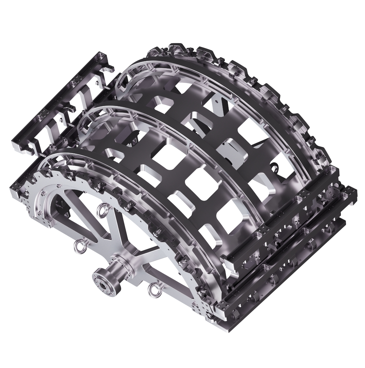
SOLUTIONS / MANUFACTURING CONTEXT
Connect the part context, manufacturing risk and process boundary before selecting a tooling direction.
Discuss a requirementPART CONTEXT / RESPONSE PATH
Each path connects a recognizable part situation with a likely tooling concern and a relevant category.
Primary concern: Clamping deformation
Purpose-built workholding for stable positioning during aerospace machining, assembly and inspection.
Explore FixturesPrimary concern: Positioning deviation
Custom guidance and location tooling developed around component geometry and process requirements.
Explore JigsPrimary concern: Poor repeat accuracy
Machining support tooling for complex profiles, thin-wall components and controlled multi-axis setups.
Explore CNC ToolingPrimary concern: Low assembly consistency
Alignment and fit-up tooling that supports controlled, repeatable aerospace component assembly.
Explore AssemblyMANUFACTURING RISKS / FIVE SIGNALS
These client-identified conditions guide the requirement conversation and the verification plan.
PROJECT RESPONSE / FIVE STAGES
Review drawings, samples, processes and boundary conditions.
Develop the tooling structure and manufacturing approach.
Produce and fit components to the approved design intent.
Check datums, interfaces and positioning requirements.
Complete fit-up review and prepare the tooling for delivery.